Modification to a COCO 2 model 26-3134B to get "COLOR BASIC 1.3" and "EXTENDED COLOR BASIC 1.1"
I had more than one COCO at home. One of them was a COCO 2 model 26-3134B. It's from the Korean line, not made in USA. The board was labeled 20261058. See the following picture. It's clear it's not the usual "made in the USA" one because we see only two DRAM present instead of eight.
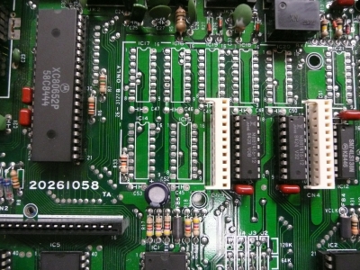
On it, it was still the original 8K PROM of "COLOR BASIC 1.1".
So I just switched to the "latest" official version from Microsoft, the "COLOR BASIC 1.3" and "EXTENDED COLOR BASIC 1.1". This is something simple to accomplished. You do that in very few steps:
1o) You unsolder the five jumpers near the BIOS PROM and you resolder them in the 128K position.
2o) You replace the ROM by a new one with the proper code in it.
3o) It's not an obligation to change the RAM to 64K. It will work as well with the original 16K.
2o) You replace the ROM by a new one with the proper code in it.
3o) It's not an obligation to change the RAM to 64K. It will work as well with the original 16K.
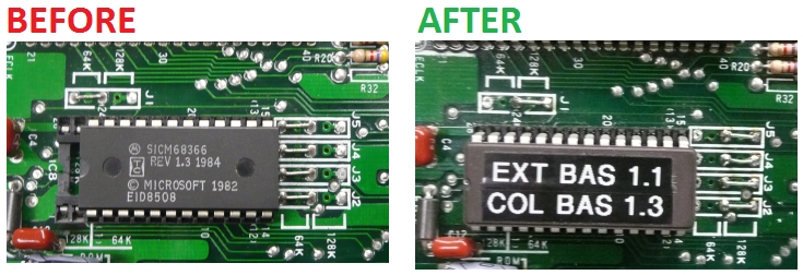
Here is a look of the jumper before and after:
The file for the "COLOR BASIC 1.3" can be downloaded from here.
The file for the "EXTENDED COLOR BASIC 1.1" can be downloaded from here.
In this model of COCO, there is just ONE program chip.
So both file must be fitted in the same chip.
So the two files are concatained together to create just one.
Under DOS, you might simply type the following to put them together:
copy /b extbas11.rom + bas13.rom /b ext11bas13.bin
So you take this file, "ext11bas13.bin", and you program your 27C128 with it.
Note: Normally that's what you do: you use a 27C128, so a 16KB chip, and you program it with that file. In my case I did not have this 27C128 part but I do have 27C256, which is a 32KB chip. So all I did is to pack together two "ext11bas13.bin" files and that gives what I used to program my 27C256. This file is here.
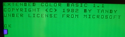
After doing so, I was ale to have my computer running again with the "COLOR BASIC 1.3" and "EXTENDED COLOR BASIC 1.1". See the following picture.
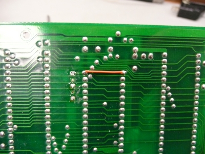
Note: In the case of a 27C256, the VPP pin is on pin 1. Even if I know that some "tolerate" to have this pin non-wired and let it floating, me, I dislike that and add a jumper wire under the board so the VPP pin is not floating and attached to a known voltage. At work, that's we do with EPROM since the last 20 years so I feel comfortable do it at home to. :-)