Modification to a COCO 2 model 26-3134B
to get a composite video output
On the same COCO 2 of the previous page, as like the other COCO 2, there was no other video output than the RF one. You needed to link the video output of the COCO 2 to a standard television via the antenna VHF input. The COCO 2 was generating a signal on the same frequencies of channel 3 or channel 4. You had a switch to select to which channel you wanted the COCO to modulate it's output. This was maybe useful or necessary in the past with standard television but today, most television has at least a composite video input. Since it was not my intention to connect my COCO on a television set to channel 3 or 4, I wanted to modify it to have a standard composite output.
This could be done without too much effort because already inside the COCO 2 there is a chip that simply by re-arranging the connexion could generate the composite signal.
The chip I am talking about is the MC1372 from Motorola. Here is a link to its datasheet.
From a few places on the web, we could find an article about that conversion. It's from the magazine "Hot Coco". It's page 98 from Auguest 1983, an article from Martin H. Goodman. We see there the following suggested modification:
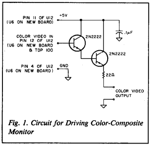
Unfortunately, in my case, this modification did not work. According to the text of the article, all I needed to do was to solder wires to pickup the signal on pin 12 of the chip without other modification. Unfrtunately, this, did not work as far as I tried. I suspect that it was because the COCO 2 I was using was a Korean version and the chip might have been wired differently than the previous flavors of the COCO 2. It was maybe pluggued in such way to generate himself the required RF signal with few passive component around.
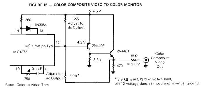
But since I needed have a composite output from my COCO, since I would prefer to not use it with a true television with VHF antenna input, I decided to remove the RF metal box where the modulator circuit is inside the COCO 2 and replace it by a circuit I've seen in one page of the datasheet of the MC6847, the video controller used inside the COCO 2. Here is an image of that circuit:
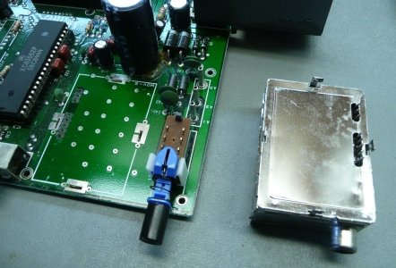
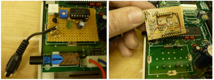
So I first unsolder the original modulator box.
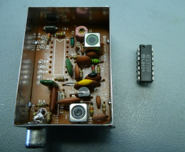
I unsoldered the MC1372.
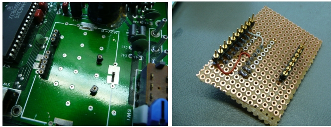
I arrange my piggy-back board to be connected on the PCB of the COCO 2.
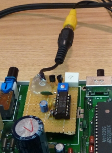
So at the end it gave me this. It's not as pretty as I would like, but it least it's functionnal and now my COCO 2 can be connected on a standard monitor with a composite input. There is one potentiometer that help to ajust the DC level of the signal and one other potentiometer to adjust a little the overall range of the signal.
I know it won't help if I need to resolder anything but to try to prevent damage in case I pull out too much my cable solder on that, I used a glue gun to try to tight there the cable output.
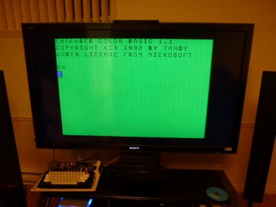
To conclude I connected the COCO on the big Sony television to see if my output would work also on it. It did.
Update!
Brian from Australia sent me a mail back in December 2020 saying he got inspiration from my page to build his own converter.
See his message:
See his message:
Hi Denis,
I also have the same model of TRS-80 as you. I also hunted all over the internet for information on a working mod. Luckily I found your website :) I have now successfully built a composite video mod and it is working wonderfully. I had to replace my RF modulator as it was faulty.
I just wanted to say thank you so much for sharing your work to the rest of us,
Thank you, stay safe and have a merry Christmas.
Brian.
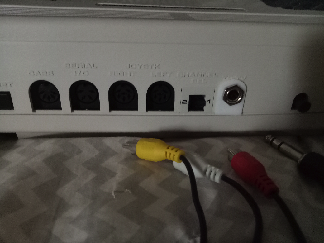
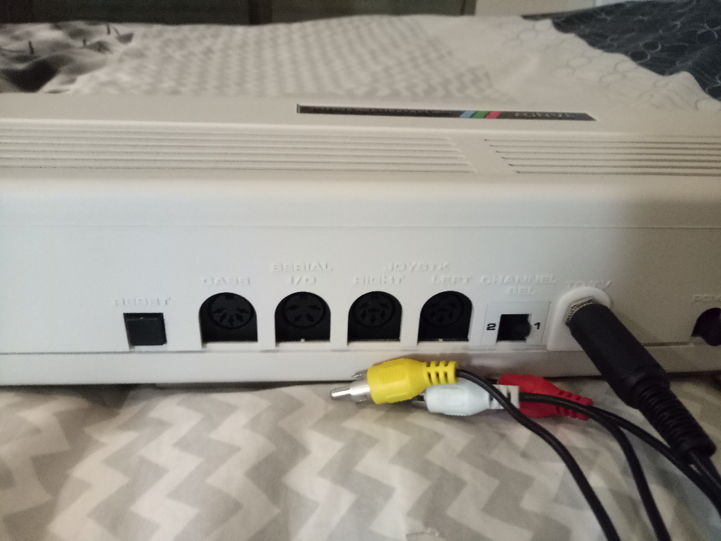
Then, he shared some pictures. It is looking much better than mine! He adapted it to a stereo jack and also designed a kind of nice looking bezel so there is no bad looking empty space caused by the modulator removing.
See his message message, pictures and a link to his 3D .stl file.
See his message message, pictures and a link to his 3D .stl file.
Hi Denis,
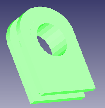
Sorry for taking so long to get back to you. I have attached some pictures as requested and as you can see I used a 6mm stereo jack for the video and audio. I also made a small cover for the jack and to cover the gap left by removing the RF modulator. I have also attached the STL, don’t know if you will have any use for it but feel free to put it on your web site for other to use if you like.
Thanks again and stay safe.
Brian.