
Modification to a COCO 2 model 26-3026
to get "COLOR BASIC 1.3" and "EXTENDED COLOR BASIC 1.1"
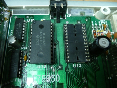
I had more than one COCO at home. One of them was a COCO 2 model 26-3026. It's a line that was made in the USA. The board was labeled 8709416. See the following picture. It's the model with the 8 chips of DRAM memory. Each DRAM is responsible for 1 bit.
On it, it was still the original 8K PROM of "COLOR BASIC 1.1".
I wanted to switch to the "latest" version of BASIC to get "COLOR BASIC 1.3" and "EXTENDED COLOR BASIC 1.1".
On my board, what was installed, was simply one PROM, the "COLOR BASIC 1.1" (at position U12)
The missing one was for the "EXTENDED COLOR BASIC" (at position U13).
The one installed for "COLOR BASIC" is mapped from &HA000 to &HBFFF.
The one missing for "EXTENDED COLOR BASIC" is mapped from &H8000 to &H9FFF.
I always found confusing that the first required one, the "COLOR BASIC" is mapped higher is memory. If it would be me, I feel I would have done the opposite.
Looking at the previous picture you might say that all I need to do is to program two new EPROM and place them in the socket.
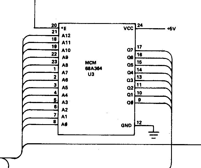
Unfortunately, it's not so simple. Why? Because these chips are very rare now, thirty years later... Certainly I can still find on e-Bay old EPROM like the 27C64 or 27C128. But look at the sockets: there are 24-pins! The "COLOR BASIC" installed on left has 8K and mapped on 24-pins. Normally the 8K EPROM I know need to have 28 pins because it cannot fit in 24. Let's figure the number of pin required: 13-pins for address, 8 pins for data, 1 pin for VCC, 1 pin for ground, 1 pin for chip select and 1 pin for output enable. So this gives at least 13+8+1+1+1+1=25 pins. How come they fitted this in 24? It's because their old PROM has only ONE input called "E" for doing both chip select and output enable! See from the schematic of the COCO-2:
Unfortunately, it's not so simple. Why? Because these chips are very rare now, thirty years later... Certainly I can still find on e-Bay old EPROM like the 27C64 or 27C128. But look at the sockets: there are 24-pins! The "COLOR BASIC" installed on left has 8K and mapped on 24-pins. Normally the 8K EPROM I know need to have 28 pins because it cannot fit in 24. Let's figure the number of pin required: 13-pins for address, 8 pins for data, 1 pin for VCC, 1 pin for ground, 1 pin for chip select and 1 pin for output enable. So this gives at least 13+8+1+1+1+1=25 pins. How come they fitted this in 24? It's because their old PROM has only ONE input called "E" for doing both chip select and output enable! See from the schematic of the COCO-2:
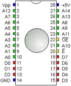
So here is what I decided. I would fit both "COLOR BASIC" and "EXTENDED COLOR BASIC" in the same EPROM. It would be what I could still find, so a 27C256. Obviously this could not fit "as is" inside the socket since this chips has 28 pins and also, a different pinout as you can see here.
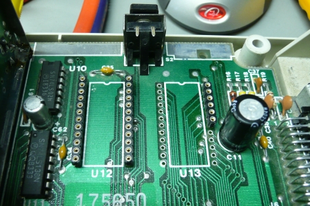
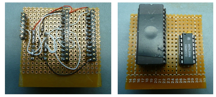
So I unsoldered the two sockets from the board and solder machined pin strip socket.
Then I wired the 28-pins socket on a small wired-board. It was not so complicated because I installed my header next to the socket of the EPROM and for the pins that were with the same pinout, I simply needed to add a solder bridge between to attached the pins together. Then, only a few wires to "correct" the A11 and A12 lines, the CE and OE lines and the VCC obviously. I needed to add a AND-gate, the 74LS08, that control the Chip Select and Output Enable lines of the EPROM. It does a AND between the original Chip Select of projected PROM originally designed to be on the board. So with the 74LS08 gate, when either one of the PROM was intedted to be selected, my new single one would be selected.
Once installed on the board, it's visible that it's not "from the company", but at least it works!
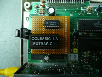
The "EXTENDED COLOR BASIC 1.1" is proudly displayed!

I use the same binary file to program my 27C256 as the one I described in the first page of this section.
